An Introduction to Sequence Diagrams
Sequence diagrams are standardized diagrams used by Solutions Architects to describe the way that different components of a software system interact with one another over time.
Today, it’s very rare to build a digital product that won’t connect to other tools and services. Usually, something like a marketing website will integrate with a tool like HubSpot and a platform like Google Analytics. As the complexity of an application grows, there are more components working together.
This is where the sequence diagram comes in.
How to Read Sequence Diagrams
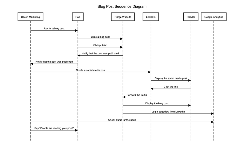
Here is an example sequence diagram I created for this post:

Sequence diagrams show the flow of information through a system
The components are listed at the top of the diagram in boxes. Their names are inside the box, and they have lines extending vertically below the boxes. These are the parts of the system that need to communicate with one another for the application to work as expected.
Arrows are drawn between the vertical lines to indicate actions where data or information needs to be transmitted between components. The arrows are labeled with descriptions of the type of information that will be sent back and forth. The arrows are all one-directional, that is, they don’t have arrowheads on both ends. If one component sends information to another component which sends information back to the first component, the second component will have its own arrow and its own description extending to the first component.
You read the diagram from top to bottom. At the top of the diagram, the first arrow shows the first action in the sequence. This action occurs between the component whose vertical line the arrow starts on and the component whose vertical line the arrow ends on. The next arrow from the top is the second arrow in the sequences. And so on.
You can introduce more complexity into the diagram, as well. You might show conditions under which certain parts of the sequence run. Something like this would look like a box around some arrows on the diagram with a label indicating the condition for the enclosed sequence.
Sequence diagrams can describe a whole software system, or they can describe a part of the system that is hard to understand or to explain in words. The purpose of the diagram is for the people who make it and who read it to understand each other. So, if you read a sequence diagram and don’t understand what it describes, ask your Solutions Architect for more clarity.
How to Make Sequence Diagrams
As long as you follow the conventions above, there is no wrong way to create a sequence diagram. Sequence diagrams do have a unified modeling language (UML) specification, which can provide better, more authoritative advice than I can offer in this blog post.
Again, the purpose of these documents is to communicate ideas. To that end, I think it’s very important to follow conventions. Many people choose to make diagrams in software that provides a lot of flexibility. My preference is to model in software that is strongly opinionated about how diagrams should be created.
My favorite tool for sequence diagramming is called SequenceDiagram.org, which is a text-based diagramming tool that generates a diagram. It’s fairly easy to start using, because the diagram updates with every line of valid text you add to the markup in the sidebar. One downside of this tool is that you can’t set up an account. So, you have to remember to save your diagrams to some other storage location or you’ll lose them. Years ago this would have been common sense, but today most online tools automatically save your work so it takes a little getting-used-to.
If I’m working with a more free-form tool, I prefer to use LucidChart. LucidChart has a nice snap-to-grid feature that some other tools like Diagrams.net (formerly Draw.io) don’t. LucidChart still comes with its share of headaches, though, like the way lines snap awkwardly around shapes. It’s a good tool for arbitrary diagramming, but not the ideal resource for creating sequence diagrams.
Lastly, don’t underestimate the value of something truly unconstrained, like a physical whiteboard or whiteboard simulator. For sequence diagramming, my favorite digital whiteboard is Limnu. It has a few unusual user experience patterns, but once you get into a whiteboard it really feels like you’re drawing, down to the styling of “marker” lines. You can share access to a board and collaborate. During a working session, this can be one of the best ways to get ideas down quickly. I don’t typically do rapid prototyping of sequence diagrams, but if I did, Limnu would be my choice.
Next Steps:
- Learn more about the parts of a sequence diagram an how they should work (Visual Paradigm)
- Dive into the primary source on creating UML sequence diagrams (Object Management Group)
- Try creating your own sequence diagram (SequenceDiagram.org)
